Spine-leaf has become the dominant topology for IP media networks in broadcast facilities, outside broadcast trucks, and stadium infrastructure. It is predictable, scalable, and well-suited to the low-latency, high-bandwidth demands of uncompressed media. But a spine-leaf fabric is, by design, a closed system. The border router is what connects it to everything else.
Spine-Leaf in Brief
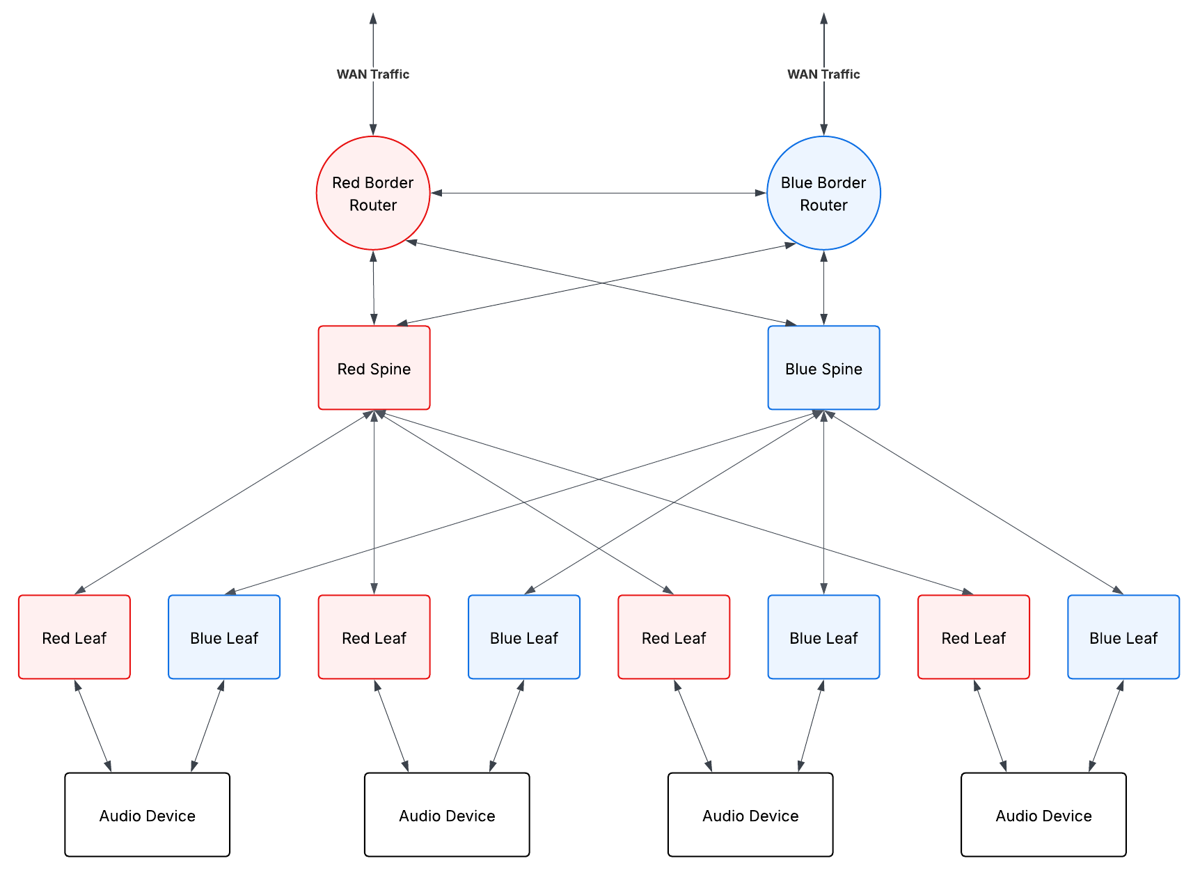
In a spine-leaf topology, every leaf switch connects to every spine switch. There are no direct connections between leaf switches, and no direct connections between spine switches. Traffic between any two endpoints always takes the same number of hops - leaf to spine to leaf - which gives you consistent, predictable latency across the fabric.
Leaf switches are the access layer. Servers, encoders, cameras, audio devices, and other endpoints connect here. Spine switches form the transport layer, providing high-bandwidth interconnect between all the leaves. The result is a non-blocking, east-west optimised fabric that scales horizontally by adding more leaves and spines.
What spine-leaf does not natively provide is a connection to anything outside the fabric. That is where the border router comes in.
What a Border Router Does
The border router sits at the edge of the spine-leaf fabric, connecting it to external networks. In a media facility, those external networks might include:
- WAN circuits carrying contribution feeds from remote sites
- Internet uplinks for cloud connectivity or remote production workflows
- Inter-facility links to other broadcast centres
- MPLS circuits to venues or outside broadcast units
- Management and corporate networks that are kept separate from the media fabric
The border router is responsible for terminating these external connections and exchanging routing information between the internal fabric and the outside world. It enforces the boundary between trusted internal infrastructure and external networks, applying routing policy, traffic filtering, and access control at the edge.
Routing and BGP
Within a spine-leaf fabric, routing is typically handled with a protocol like OSPF or IS-IS - link-state protocols that are well-suited to the predictable, symmetric topology. These protocols converge quickly and distribute routes efficiently within the fabric.
At the border, you need to exchange routes with external networks that may be running different routing domains, managed by different organisations, or presenting a large and complex routing table. This is where BGP (Border Gateway Protocol) is typically used. BGP is the protocol of the internet and of inter-site connectivity. The border router runs BGP externally, translating between what the external networks advertise and what the internal fabric needs to know.
In practice, this often means the border router redistributes a default route or a summary route into the internal fabric, rather than flooding the full external routing table into every spine and leaf. This keeps the internal routing simple and the convergence fast.
Traffic Segmentation and Policy
Media networks carry traffic with very different characteristics and security requirements. Uncompressed video and audio flows need low latency and predictable forwarding. Management traffic needs to be reachable but isolated from media flows. External connections need to be controlled so that nothing unintended enters or leaves the fabric.
The border router is where traffic policy is enforced at the network edge. This typically involves:
Route filtering - controlling which prefixes are accepted from external peers and which internal prefixes are advertised externally. You generally do not want to advertise your internal media subnets to the internet, and you do not want to accept arbitrary routes from an external circuit that could redirect internal traffic.
Access control - restricting which protocols and ports are permitted to cross the border. Media flows use specific protocols (RTP, RTSP, SRT, NDI, RIST) on known ports. The border router can enforce that only expected traffic types are permitted inbound.
Traffic shaping and QoS remarking - WAN circuits often have bandwidth constraints. The border router may need to shape outbound traffic to stay within committed rates, and remark DSCP values to match the QoS policy of the external network.
Multicast at the Border
SMPTE ST 2110 and AES67 media flows use IP multicast. Within the spine-leaf fabric, multicast is managed with PIM (Protocol Independent Multicast) and IGMP, with the fabric efficiently replicating streams only to the leaves that have subscribed receivers.
At the border, multicast requires careful handling. Multicast does not naturally extend across routing boundaries. If you need to send or receive multicast streams across a WAN, you have several options - PIM over GRE tunnels, MSDP between PIM domains, or encapsulation using a protocol like RIST or SRT that wraps multicast content in a unicast transport.
The border router is where this translation happens. It is the point at which a multicast stream destined for an external site is intercepted, encapsulated, and forwarded as unicast across the WAN - and where the reverse conversion happens on the receiving end.
Timing Considerations
PTP (Precision Time Protocol, IEEE 1588) is the timing backbone of ST 2110 networks. A grandmaster clock distributes timing to all devices in the fabric, keeping audio and video flows synchronised to sub-microsecond accuracy.
The border router does not participate in PTP directly, but it has implications for timing. PTP does not cross routing boundaries - it operates at Layer 2 within the fabric. If you are connecting two facilities that both run ST 2110, they each need their own PTP grandmaster, typically disciplined by a common GNSS reference. The border router carries the media flows between them, but timing is handled separately at each end.
This is worth understanding when designing multi-site or hybrid cloud ST 2110 workflows. The network can connect the facilities, but synchronisation requires a separate timing architecture at each site.
Redundancy
In a production environment, a single border router is a single point of failure for all external connectivity. The standard approach is to deploy border routers in pairs, with each router maintaining its own connections to the external network. ECMP (Equal-Cost Multi-Path) or routing protocol failover provides automatic switchover if one router fails.
For critical connections - primary contribution feeds, main WAN uplinks - it is also worth considering physical diversity. Two border routers on different power circuits, connected to different WAN provider handoffs, provides resilience against both hardware failure and provider outage.
Where This Fits in Practice
In a fixed broadcast facility, the border router is typically a dedicated piece of hardware - a high-capacity router from Cisco, Juniper, or Arista - sitting at the top of the network, connected to the spine layer and to the facility’s external circuits.
In an outside broadcast or temporary deployment, the boundary is often less distinct. A single device may act as both fabric edge and WAN gateway, handling contribution circuit termination, routing, and media gateway functions in one box. The logical role is the same even if the physical implementation is more compact.
Understanding where the border is, what crosses it, and how traffic is controlled at that boundary is fundamental to designing IP media networks that are both functional and secure. The spine-leaf fabric handles internal media distribution efficiently - the border router determines how that fabric connects to the rest of the world.